Welcome to RTKSurvey.com

GNSS RTK Base and Rover Explained: Setup, Corrections & Field Tips
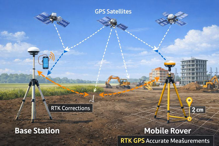
A GNSS RTK system can produce highly precise field coordinates, but reliable results depend on more than switching on a receiver and waiting for a fixed solution.
The base station must use appropriate reference coordinates. The rover must receive compatible correction data. Both units need suitable satellite observations, and the field software must apply the correct coordinate settings.
When one of these elements is configured incorrectly, a system may appear to operate normally while producing coordinates that do not match the project control.
This guide explains the practical relationship between a GNSS RTK base and rover, how to prepare a local base-rover setup, when to use UHF radio or NTRIP corrections, and which checks help surveyors identify problems before collecting project data.
What Does the Base Station Actually Do?
A GNSS RTK base station is a receiver operating at a reference location.
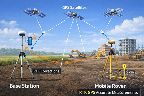
It observes satellite signals and generates correction information based on its configured reference position and the measurements it receives.
The correction data is then delivered to compatible rover receivers.
Why Base Coordinates Matter
The base station's coordinates are fundamental to the positioning result.
If a base is assigned incorrect coordinates, the rover may still obtain an RTK fixed solution while its calculated positions are shifted relative to the required reference system.
This is why an apparently successful initialization is not proof that the entire survey setup is correct.
For work tied to an established control network, use reference coordinates determined and verified through an appropriate survey procedure.
Known-Point and Autonomous Base Setup
A base station can be configured using known coordinates or an automatically estimated position, depending on the equipment and field workflow.
A known-point setup uses coordinates established for the occupied station.
An autonomous setup estimates the base position from GNSS observations. It may allow a local relative survey to begin, but the estimated position should not be assumed to provide survey-grade absolute coordinates.
Where project coordinates are required, the reference position must be properly established or the survey must be transformed and checked against suitable control.
What Does the GNSS Rover Do?
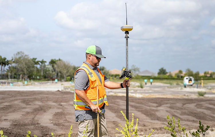
The rover is the receiver moved between survey points.
It combines its own satellite observations with correction information to estimate its position relative to the reference system.
A field controller or integrated interface allows the operator to manage the survey, view solution quality and record measurements.
Fixed and Float Solutions
An RTK fixed solution generally indicates that the carrier-phase ambiguity resolution process has succeeded.
A float solution indicates that the ambiguities have not been resolved to the same level.
These states are important, but they are not complete quality assessments.
A fixed solution can still be affected by incorrect reference coordinates, unsuitable coordinate settings, antenna-height errors or poor observation conditions.
For this reason, surveyors should verify coordinates against independent control rather than relying only on the displayed solution status.
How RTK Corrections Reach the Rover
A base and rover need a compatible method of delivering correction data.
Two common approaches are local radio transmission and internet-based delivery.
UHF Radio Corrections
In a local UHF setup, the base transmits correction messages over a radio link, and the rover receives them through compatible radio equipment.
This can be useful on projects where mobile internet coverage is unavailable or unreliable.
Radio performance depends on factors such as antenna placement, terrain, obstructions, equipment configuration and permitted transmission power.
The base and rover must use compatible frequencies, communication settings and correction formats.
Local radio operation must also comply with the applicable regulations in the country or region of use.
NTRIP Corrections
NTRIP is a method for delivering GNSS correction data over an internet connection.
A rover or connected controller can receive corrections from a compatible caster, often operated by a reference-station network or correction-service provider.
A local base may also transmit corrections through an internet-based system when supported by the equipment and service configuration.
Using NTRIP does not automatically mean that the corrections come from a network RTK solution. The stream may originate from a single reference station or a network service.
The rover must use the appropriate correction stream and coordinate reference settings for the project.
UHF Radio vs NTRIP: Which Should You Choose?
The better option depends on the working environment.
UHF may be practical for remote areas where a local base can be established but cellular coverage is limited.
NTRIP may simplify operations where a suitable correction service and reliable internet connection are available.
Before choosing, confirm correction coverage, compatibility, project accuracy requirements, service availability and any operational restrictions.
Step-by-Step: Preparing a Local RTK Base Station

Exact menu names and procedures differ between manufacturers. The following sequence describes the general planning and verification process rather than model-specific operating instructions.
Step 1: Select a Suitable Base Location
Choose a stable location with good sky visibility.
Avoid placing the receiver unnecessarily close to large reflective surfaces, substantial obstructions or sources of radio interference.
The site should also be safe from accidental movement, construction traffic and equipment disturbance.
Step 2: Set Up the Tripod and Receiver
Install the tripod securely and mount the receiver using the appropriate adapter.
Center and level the setup as required by the mounting arrangement and survey procedure.
Confirm the antenna reference point and measure the antenna height using the method specified by the equipment manufacturer.
Incorrect antenna-height entries can directly affect the resulting coordinates.
Step 3: Configure the Reference Coordinates
Enter the verified reference coordinates and the correct antenna information.
Confirm that the coordinates use the intended reference frame and that the software is configured consistently.
Do not use an unverified autonomous position as if it were an established project control point.
Step 4: Configure the Correction Output
Select the supported correction format and communication method.
For a radio link, check the applicable frequency, channel and communication settings.
For internet transmission, check the connection, caster settings and required authentication.
Confirm that the base is actually transmitting correction messages.
Step 5: Verify the Setup Before Production Work
Connect a compatible rover and observe a suitable known point.
Compare the measured coordinates with the accepted control values.
If the difference exceeds the project's acceptance criteria, investigate the setup before collecting survey data.
Setting Up the Rover for Field Measurements
After the base is operating, configure the rover to receive the appropriate correction source.
Match the Correction Configuration
Confirm that the rover can interpret the correction messages being transmitted.
For a UHF connection, the communication settings must match the base system.
For NTRIP, confirm the correct service, mountpoint, login information and network connection.
A connected device is not necessarily receiving usable corrections, so inspect the rover's correction status and message age.
Confirm the Coordinate System
The rover's coordinate reference system, transformation and localization settings must match the project requirements.
A coordinate mismatch can cause systematic errors even when the satellite solution appears stable.
Where a site calibration is used, apply only verified parameters suitable for the working area.
Enter the Correct Pole Height
Check the physical pole height and the measurement convention expected by the receiver software.
For receivers with tilt compensation, follow the manufacturer's setup and verification procedure.
Tilt compensation does not remove the need for correct pole-height information or appropriate quality checks.
Five Problems That Can Affect an RTK Base-Rover Survey
1. The Rover Receives No Corrections
Possible causes include incorrect radio settings, an unavailable NTRIP stream, weak communications or incompatible message formats.
Start by confirming that the base or correction service is transmitting and that the rover is receiving the expected data.
2. The Rover Remains in Float
Poor satellite visibility, multipath, unfavorable geometry or unsuitable correction conditions may prevent ambiguity resolution.
Move to a location with better sky visibility when possible and review the receiver's quality indicators.
Do not assume that repeatedly restarting the receiver will solve an environmental limitation.
3. The Rover Shows Fixed but Coordinates Are Wrong
This can happen when the reference position, coordinate transformation, antenna height or project configuration is incorrect.
Check the entire coordinate chain, beginning with the base reference position and the project's control requirements.
4. The Radio Link Is Unstable
Terrain, obstructions, antenna configuration, interference and distance can affect radio communication.
Review the physical link and legal operating settings rather than assuming that increasing transmission power is always an appropriate solution.
5. Measurements Vary Near Buildings or Trees
Obstructed and reflected satellite signals can degrade GNSS observations.
Allowing the receiver to display a fixed solution does not eliminate these effects.
For difficult locations, use additional observations, independent checks or an alternative surveying method such as a total station when appropriate.
Field Checks Before Collecting Survey Points
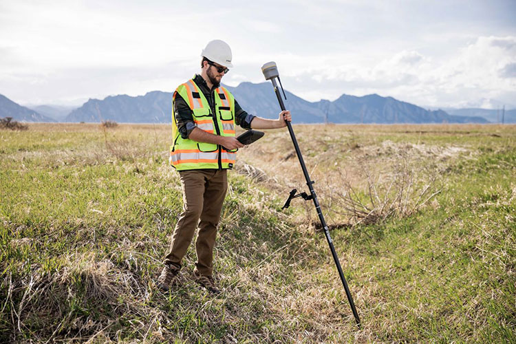
A practical quality-control routine should be established before the crew starts production measurements.
Before Leaving the Office
Confirm receiver, controller and software compatibility.
Check correction-service access or radio configuration.
Prepare the correct coordinate system and project files.
Verify that batteries and charging equipment are ready.
Confirm the control points and required survey tolerances.
At the Base Station
Confirm the physical stability of the setup.
Verify the reference coordinates.
Measure and enter the antenna height correctly.
Check correction transmission.
Record the setup details needed for the survey documentation.
At the Rover
Confirm the selected correction source.
Review solution status and correction age.
Verify pole height and applicable tilt settings.
Measure a known control point.
Perform repeat or independent observations as required.
Before Finishing the Survey
Return to a suitable control point or perform another independent verification according to the project procedure.
Record any unexpected differences and investigate them before finalizing the data.
A consistent field checklist helps reduce the risk of discovering coordinate problems after the crew has left the site.
Do You Always Need Your Own RTK Base Station?
No.
A local base station is one way to obtain RTK corrections, but a suitable network correction service may allow a rover to operate without a separate base owned by the survey team.
A local base may be useful when correction-service coverage is limited, when the project requires a controlled local reference setup or when internet connectivity is unreliable.
A network service may reduce the amount of equipment that must be installed each day.
The decision should consider reference-frame compatibility, coverage, communications, operating costs and project control requirements.
Choosing GNSS Equipment for a Base-Rover Workflow
When selecting GNSS receivers, confirm that the proposed configuration supports the required operating modes.
Important questions include:
Can the receiver operate as a base, rover or both?
Which correction message formats are supported?
Does the equipment support the required radio or NTRIP workflow?
Are the radio bands and regional configurations suitable for the project?
Is the field controller compatible with the receiver and survey software?
Which tripods, poles, adapters and communication accessories are required?
What technical support is available for configuration and troubleshooting?
Avoid purchasing equipment based only on satellite channel counts or advertised positioning accuracy.
A reliable working configuration requires compatible hardware, software, correction services and field procedures.
Explore GNSS RTK Equipment at RTKSurvey.com
RTKSurvey.com supplies GNSS receivers and surveying accessories for land surveying, construction and mapping applications.
Browse our GNSS Receivers category to explore equipment options, or visit Surveying Accessories for tripods, survey poles and related field equipment.
For a broader introduction to the technology, read What Is an RTK GNSS Receiver? A Practical Guide for Surveying.
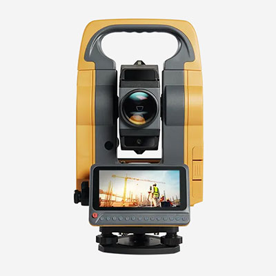
If your team works in areas with limited satellite visibility, our guide to GNSS RTK vs Total Station explains when an optical surveying instrument may be more suitable.
Frequently Asked Questions
What Is the Difference Between an RTK Base and Rover?
The base operates at a reference location and provides correction information. The rover receives compatible corrections and uses them with its own GNSS observations to calculate positions.
Can One GNSS Receiver Work as Both Base and Rover?
Some GNSS receivers support both operating modes, but capabilities vary by model and configuration. Confirm the supported functions before purchasing.
Is NTRIP More Accurate Than UHF Radio?
Neither communication method is inherently more accurate simply because of how corrections are delivered. Positioning performance depends on the correction source, reference coordinates, observation conditions and overall system configuration.
How Far Can an RTK Rover Work from a Base?
There is no universal maximum distance. Practical limits depend on the correction method, radio coverage, baseline-dependent errors, atmospheric conditions and required accuracy.
Why Is My RTK Rover Fixed but Not Matching Control Points?
Possible causes include incorrect base coordinates, inconsistent coordinate systems, unsuitable transformations or antenna-height errors. The setup should be checked against verified project control before measurements are accepted.
Final Thoughts
A GNSS RTK base-rover system is only as reliable as its reference coordinates, correction connection and field verification procedures.
A stable base setup, compatible communication settings and a correctly configured rover provide the foundation for efficient surveying. Independent control checks help confirm that the resulting coordinates are suitable for the project.
Understanding these practical requirements makes it easier to select compatible equipment, troubleshoot field problems and reduce avoidable measurement errors.