Welcome to RTKSurvey.com

RTK Fixed but Wrong Coordinates? 7 Causes and How to Check Them
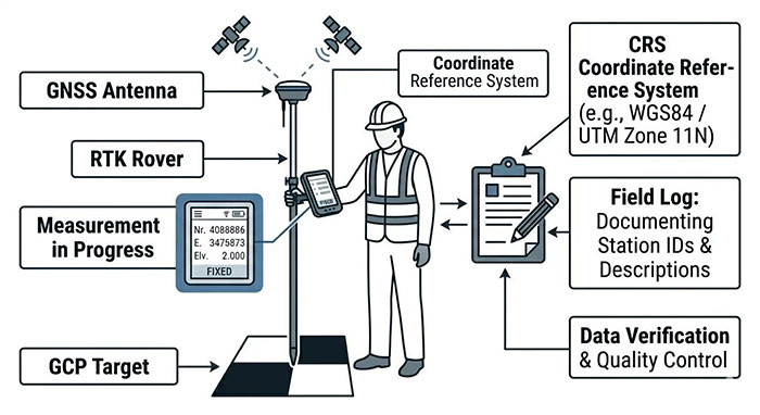
Your GNSS rover shows RTK Fixed. The correction link is active, the controller reports a small estimated position error, and the coordinates remain stable.
Then you occupy a known survey control point and discover that the position is wrong.
This is one of the more confusing problems in RTK surveying. The receiver appears to be working correctly, yet the result does not match the coordinates required by the project.
The explanation is that an RTK fixed solution and an accurate project coordinate are not the same thing. A fixed solution indicates that the receiver has resolved the carrier-phase integer ambiguities used in its positioning calculation. It does not independently verify the base station coordinates, coordinate reference system, antenna height or local site calibration.
Before changing settings or repeating an entire survey, examine how the measured coordinates differ from known control. The pattern of the error often provides a better starting point than the receiver's status screen.
Start with the Error Pattern, Not the FIX Indicator
Imagine a survey crew establishing control for a construction site.
The rover achieves RTK Fixed in an open area. Its estimated horizontal precision is reported as 0.012 m. However, when the crew checks an established control point, the measured easting differs from the accepted project coordinate by approximately 0.42 m.
A second independent control point shows a similar difference.
The crew repeats several observations. The results agree closely with one another, but they still do not agree with the project control.
This is a useful diagnostic clue.
The receiver may be measuring consistently within its current reference setup while that setup is incorrectly tied to the project's coordinate system.
Now consider a different situation: the rover checks correctly at two open-sky control points but produces inconsistent coordinates beside a steel-framed building.
That pattern suggests a different investigation, focusing on the observation environment, satellite tracking and the reliability of the fixed solution.
Before troubleshooting, separate the symptoms into three groups:
| Observed problem | Where to investigate first |
|---|---|
| Several control points show a similar horizontal offset | Base coordinates, reference frame, project transformation |
| Horizontal coordinates agree, but elevations are consistently wrong | Antenna height, vertical datum, geoid model |
| Errors vary between occupations or appear near obstructions | Multipath, satellite geometry, correction quality, possible incorrect fix |
These patterns are clues, not definitive diagnoses. More than one error can exist at the same time.
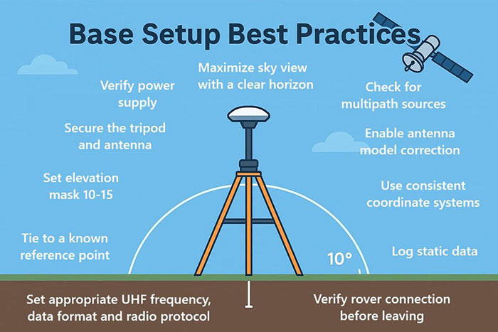
1. Incorrect GNSS RTK Base Station Coordinates
A local GNSS RTK base station provides reference observations and position information that the rover uses to determine its position relative to the base.
The rover can calculate a precise relative baseline even when the coordinates assigned to the base station are wrong.
That distinction is fundamental.
Known-Point Setup vs Autonomous Base Setup
When a base station occupies a surveyed control mark, its reference position should be established using appropriately determined coordinates in the correct reference frame.
If the operator accidentally enters the wrong coordinates, selects the wrong control point or uses an incompatible coordinate reference, the rover positions can inherit a systematic error.
A different problem arises when the base is initialized using its own autonomous GNSS position.
An autonomous position may be sufficient for certain relative surveying tasks, depending on the workflow. It does not automatically establish an accurate absolute position in the project's control network.
A crew can therefore obtain repeatable RTK measurements that are displaced from established site coordinates.
How to Check the Base Station
Begin with the actual reference position being broadcast by the base, not simply the coordinates written in the field notebook.
Confirm the base station point identification, coordinate values, reference frame and antenna setup.
If the base is installed over a known mark, verify that the correct mark was occupied and that the coordinates correspond to the required reference frame and epoch.
If the base was initialized autonomously, determine how the project intends to establish its absolute coordinate reference. That may require an appropriate control survey, reliable correction service or post-processed reference position.
Do not compensate for a wrong base position by arbitrarily shifting individual rover points.
A base coordinate problem should be corrected at the reference or project-configuration level, with previously collected observations assessed for their impact.
2. The Wrong Coordinate Reference System or Transformation
A GNSS receiver can report a mathematically valid position that does not match a construction project's grid coordinates.
The problem may be in the transformation between the global GNSS reference frame and the local coordinate system used for engineering work.
This is particularly relevant when a project combines data from GNSS, total stations, CAD drawings and existing control networks.
Datum, Projection and Epoch Are Not Interchangeable
A geodetic datum or reference frame defines how positions are referenced to the Earth.
A map projection converts geographic positions into planar coordinates.
A coordinate epoch identifies the time reference of coordinates in systems where positions can change over time.
These are related but distinct elements of a coordinate definition.
Selecting the correct projection name does not necessarily mean that the entire coordinate system is configured correctly.
Likewise, two coordinate sets may use similar numerical formats while referring to different datums or local engineering grids.
A Practical Site Example
Suppose a contractor receives control coordinates from the project surveyor and imports them into the data collector.
The GNSS rover uses a network correction service, and RTK Fixed is achieved without difficulty.
However, the controller is configured for a different reference frame or an incorrect site transformation.
The displayed coordinates may be stable and internally consistent, yet fail to match the project's established control.
The appropriate response is to verify the coordinate system definition supplied with the project, including the required datum, projection, units, transformation and any relevant epoch information.
For a network RTK workflow, the reference frame used by the correction service must also be understood.
Do not assume that selecting a coordinate system with a familiar regional name resolves every transformation requirement.
3. Incorrect Rover or Base Antenna Height
When the horizontal position appears correct but elevations are consistently wrong, antenna height is one of the first settings to inspect.
An RTK receiver determines the position of its antenna reference geometry. The survey software then uses the entered antenna or pole height to calculate the position of the ground point.
If the entered height is wrong, the calculated ground elevation will also be wrong.
Example: A 200 mm Height Difference
A rover is mounted on a vertical survey pole with a correctly defined antenna reference height of 2.000 m above the surveyed point.
The controller is mistakenly configured for 1.800 m.
Assuming the software uses that vertical reference height directly, the calculated ground elevation will be approximately 0.200 m too high.
The rover may continue to show RTK Fixed throughout the observation.
The issue is not necessarily a failure of carrier-phase positioning. It is an incorrect conversion from the antenna position to the surveyed point.
Check the Measurement Reference
Different receivers and mounting arrangements may use different antenna-height measurement methods.
The software may require a vertical height to an antenna reference point, a measured slant height or a height referenced to a specific mark on the receiver or adapter.
These values should not be interchanged without applying the appropriate geometry.
For a local base station, an incorrect base antenna height can also affect the reference position used by the rover.
Check the physical pole or tripod setup, the selected antenna model, any adapters and the measurement method specified by the equipment documentation.
If a crew changes pole length during the day, the controller setting must reflect the new configuration.
4. Wrong Geoid Model or Vertical Datum
GNSS positioning naturally provides height relative to a reference ellipsoid.
Engineering projects frequently require elevations referenced to a vertical datum, often represented through a geoid or other vertical transformation model.
These height systems are not interchangeable.
A project may show acceptable horizontal agreement while displaying a substantial elevation difference because the required vertical transformation is missing or incorrect.
How to Recognize the Problem
Suppose several control points have horizontal coordinates that agree with the project values, but the RTK elevations differ systematically from published benchmark elevations.
The first question should be whether both datasets represent the same type of height.
Check whether the controller is displaying ellipsoidal height or an elevation transformed to the project's vertical datum.
Then verify the geoid model, its coverage and the vertical reference specified by the project.
Do not apply an arbitrary elevation adjustment before establishing which height systems are being compared.
A wrong antenna height and a wrong geoid model can produce superficially similar symptoms, so both should be investigated.
5. Incorrect NTRIP Correction Source or Reference Frame
Not every RTK survey uses a locally operated base station.
With network RTK, a rover may receive corrections through NTRIP from a CORS network or another correction service.
A successful connection does not automatically establish that the selected correction stream is appropriate for the project.
What the NTRIP Connection Tells You
The receiver may show that correction data is arriving and that an RTK fixed solution has been obtained.
This confirms important parts of the positioning process, but it does not independently verify the project's coordinate reference requirements.
A correction service may operate in a particular reference frame or epoch. The field software must handle the relationship between that reference and the coordinates required for the job.
What to Verify
Check the selected NTRIP mountpoint and the correction service documentation.
Confirm the reference frame, any applicable epoch information and the coordinate transformation used by the project.
Also review the correction age and connection stability.
An unsuitable reference configuration can cause systematic disagreement with project control. Delayed or interrupted corrections, on the other hand, may affect positioning quality or the ability to maintain a reliable fixed solution.
These are different problems and should not be treated as interchangeable.
6. Incorrect Site Calibration or Localization
Construction projects sometimes use a local engineering coordinate system that is established through site calibration or localization.
This allows GNSS observations to be related to project control coordinates.
However, the transformation is only as dependable as its input data, geometric configuration and suitability for the project area.
When a Localization Appears to Work
A crew may calibrate its GNSS project using a small number of control points.
The software reports acceptable residuals, and the rover begins measuring.
Later, an independent control point outside the calibration set shows an unexpected difference.
Possible causes include incorrect control coordinates, point identification mistakes, unsuitable point distribution, inconsistent vertical references or a transformation that does not adequately represent the project.
Low residuals at the points used to calculate a transformation do not necessarily prove its accuracy at independent locations.
How to Evaluate the Calibration
Review the source and quality of the control coordinates.
Check that the points are correctly identified and distributed across the work area.
Examine the transformation residuals, but also verify the result against independent control points that were not used to create the calibration.
For large or complex projects, the project surveyor should determine the appropriate transformation method and acceptance criteria.
Do not repeatedly recalibrate the site merely to make one problematic point match.
That can conceal an underlying control or configuration error.
7. Multipath, Obstructions or an Incorrect Fixed Solution
So far, most of the problems involve reference information or survey configuration.
There is another possibility: the RTK fixed solution itself may not be reliable.
A receiver can occasionally resolve carrier-phase ambiguities incorrectly, particularly under difficult observation conditions.
This is often described as a false fix or incorrect ambiguity resolution.
Where It Can Happen
GNSS signals can reflect from buildings, vehicles, metal structures and other surfaces before reaching the antenna.
These reflected signals may interfere with the direct satellite observations.
Trees, elevated structures and restricted sky visibility can also reduce the quality and geometry of the available observations.
A receiver may maintain a Fixed indication even when the actual position does not satisfy the accuracy required by the survey.
What the Error Looks Like
Unlike a reference-frame mismatch that affects an entire project consistently, observation-related problems may appear only in particular locations or change between occupations.
For example, a rover may check correctly at an open-sky control point but show inconsistent results near a building.
Moving away from the obstruction may improve the measurements.
However, a repeatable offset at a difficult location is not proof that the fixed solution is reliable. Repeated measurements can share the same environmental bias.
How to Investigate
Review satellite visibility, signal quality, correction age and the receiver's reported precision indicators.
Repeat the observation under improved sky conditions where possible.
For important control work, use independent occupations or another suitable measurement method to verify the result.
If a receiver repeatedly produces unreliable fixed solutions under conditions where comparable equipment performs satisfactorily, further investigation of its firmware, antenna, configuration and hardware may be justified.
Do not assume that every coordinate error is caused by a defective receiver.
How to Make Sure Your RTK Fix Is Accurate
The most effective verification procedure starts before production measurements.
A Fixed indicator and a small estimated precision value are useful, but neither is a substitute for checking against independent survey control.
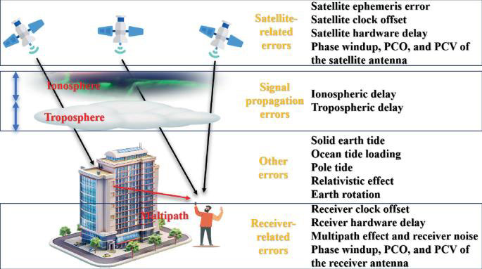
Check at Least Two Suitable Control Points
Occupy a known control point and compare the measured coordinates with the accepted values in the same coordinate reference system.
Where practical, check a second independent point in another part of the project.
The second point helps reveal whether the observed difference is consistent across the site or specific to one location.
For work requiring stronger verification, additional control and independent occupations may be necessary.
Record the Actual Differences
Do not record only "Pass" or "Fail."
Keep the coordinate differences so that their pattern can be examined.
For example, consider the following illustrative horizontal checks:
| Control point | Easting difference | Northing difference |
|---|---|---|
| CP-01 | +0.418 m | -0.126 m |
| CP-02 | +0.423 m | -0.121 m |
| CP-03 | +0.416 m | -0.129 m |
The similar differences suggest a common reference or transformation problem.
Now compare that with a different pattern:
| Control point | Easting difference | Northing difference |
|---|---|---|
| CP-01 | +0.008 m | -0.011 m |
| CP-02 | +0.012 m | +0.006 m |
| CP-03 | +0.184 m | -0.097 m |
If CP-03 is beside a reflective structure, the location and observation conditions deserve closer examination. The control mark itself should also be verified.
These examples illustrate diagnostic patterns, not universal accuracy tolerances.
Use Project-Specific Acceptance Limits
There is no single RTK accuracy threshold suitable for every surveying task.
Construction control, topographic mapping, utility surveys and deformation monitoring may require different tolerances and verification procedures.
The allowable differences should come from the project specifications, applicable surveying standards and the required accuracy of the work.
A receiver's estimated precision is not the same as a demonstrated accuracy against independent control.
Recheck After Important Changes
Repeat suitable control checks after changes that could affect the survey reference or measurement configuration.
Examples include changing the base station setup, switching correction services, loading a different project, modifying coordinate-system settings or changing antenna-height configurations.
For critical work, establish a checking procedure that also considers the time elapsed and the conditions under which observations are made.
What RTK Fix Accuracy Really Tells You
A fixed solution generally indicates that the RTK processing engine has resolved the integer ambiguities needed for high-precision carrier-phase positioning.
Under suitable conditions, this supports precise relative positioning.
However, RTK fix accuracy should not be judged from the solution label alone.
The final coordinate depends on several layers:
The quality of the satellite observations
The reliability of the ambiguity solution
The correction source and reference position
The coordinate reference system and transformations
Antenna and pole-height configuration
Site calibration and control quality
The observation procedure used in the field
A rover can be precise relative to an incorrectly positioned base station.
It can also produce a valid GNSS position that has been transformed incorrectly into a local engineering grid.
And under difficult signal conditions, even a reported fixed solution may require additional verification.
The distinction between RTK Fixed, Float and Single positioning modes is important, but it answers a different question from whether the final coordinates match project control.
A Better Troubleshooting Sequence for Field Crews
When RTK shows Fixed but the coordinates do not match, changing several settings at once makes the problem harder to identify.
Use the observed error pattern to narrow the investigation.
If multiple control points show a similar horizontal offset, examine the base station coordinates, correction reference frame, coordinate system and site transformation.
If horizontal checks pass but elevations fail, inspect antenna heights, measurement references, geoid settings and the project's vertical datum.
If the error appears only at certain locations or changes between observations, investigate satellite visibility, multipath, correction quality and the reliability of the fixed solution.
If calibration points fit but independent control does not, review the site localization, control data and point distribution.
Document the original settings before making changes. After correcting a suspected cause, repeat the relevant independent control checks.
This preserves a clear record of what was changed and whether the change actually resolved the discrepancy.
When Equipment Selection Becomes Part of the Problem
Not every RTK accuracy problem can be solved by changing receivers.
Incorrect base coordinates, coordinate systems and antenna-height settings can affect otherwise capable equipment.
However, the receiver and field software still matter.
Survey teams working around buildings, trees or other obstructions should evaluate how their equipment handles challenging GNSS observations, maintains corrections and reports solution quality.
For projects that require frequent site localization or mixed coordinate systems, the field software's coordinate-management and checking functions deserve attention.
RTKSurvey.com supplies GNSS RTK receivers for professional surveying and construction applications.
If you are planning a local reference setup, our guide to GNSS RTK base and rover configuration explains the main components of that workflow.
For a broader introduction to the technology, see What Is an RTK GNSS Receiver?.
Frequently Asked Questions
Can RTK Fixed Still Be Wrong?
Yes. A fixed solution does not independently verify the base coordinates, project datum, antenna height or site calibration. In difficult observation conditions, an incorrect fixed solution is also possible.
Why Is My RTK Fixed Position Off by One Meter?
A large, repeatable offset may indicate incorrect base coordinates, an unsuitable reference frame or an incorrect project transformation. The size of the offset alone is not enough to identify the cause. Compare multiple independent control points and examine the pattern.
How Can I Check Whether My RTK Fix Is Accurate?
Measure suitable known control points in the required coordinate system, compare the actual coordinate differences with the project's acceptance criteria and investigate any discrepancies before collecting production data.
Does RTK Fixed Mean Centimeter Accuracy?
RTK Fixed is associated with high-precision carrier-phase positioning, but it does not guarantee centimeter-level accuracy in the final project coordinates. Reference errors, setup mistakes and poor observations can still affect the result.
Can a Wrong Base Station Coordinate Affect Every Rover Point?
Yes. A wrong reference position can introduce a systematic error into rover coordinates even when the relative RTK measurements are precise.
Why Are My RTK Elevations Wrong but Easting and Northing Are Correct?
Check the antenna-height settings, height measurement reference, geoid model and vertical datum. These can affect elevations while leaving horizontal coordinates relatively unaffected.
What Is the Difference Between RTK Fixed and Float Accuracy?
Fixed and Float describe different ambiguity-resolution states. A correctly resolved RTK Fixed solution generally supports higher-precision positioning, while a Float solution retains unresolved carrier-phase ambiguities. However, actual accuracy still depends on observation quality, corrections and reference configuration.
For a detailed comparison of positioning modes, field examples and accuracy considerations, read our guide: RTK Fixed vs Float vs Single: GNSS Accuracy and Field Examples.
Final Thoughts
When a GNSS receiver reports RTK Fixed but the coordinates are wrong, the most productive first step is not to restart the receiver or replace the equipment.
Check the result against independent control and study the pattern of the differences.
A consistent project-wide offset points toward a different set of causes than an intermittent error beside a building. A vertical-only discrepancy calls for different checks from a horizontal coordinate mismatch.
RTK Fixed is an important positioning status. Reliable survey coordinates also require correct reference information, sound field procedures and independent verification.